Measures flow of high-temperature gases up to 2,500 °C
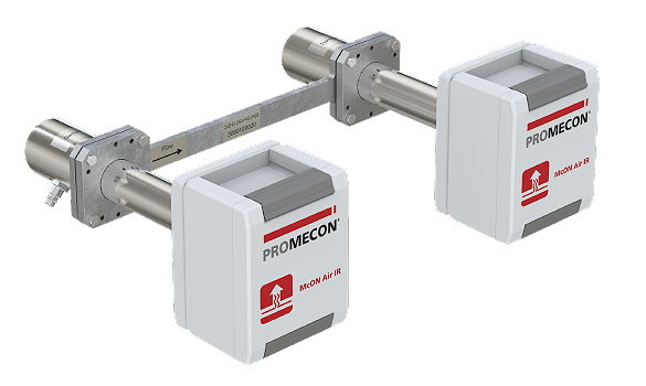
McON IR Sensors for Hot Gas Flow, Concentration, and Temperature Measurement
Used to measure the flow, concentration, and temperature of hot gases, McON IR sensors are infrared sensors based on a unique technology that highlights changes in IR radiation intensity in gases at high temperatures.
This unique technology enables continuous inline, non-contact measurement of flow rate, concentration (CO, CO2, H2O), and temperature up to 2,500 °C, even in dusty environments.
Sensors enable visualization of hot gas flow and plant improvement by applying this knowledge.
Highlights
- Responsive—measures within 2 sec.
- Non-contact IR measurement—no maintenance for parts in contact with gas
- Average values within a duct can be determined from inline process gas measurement
- Measures high-temperature gases up to 2,500 °C
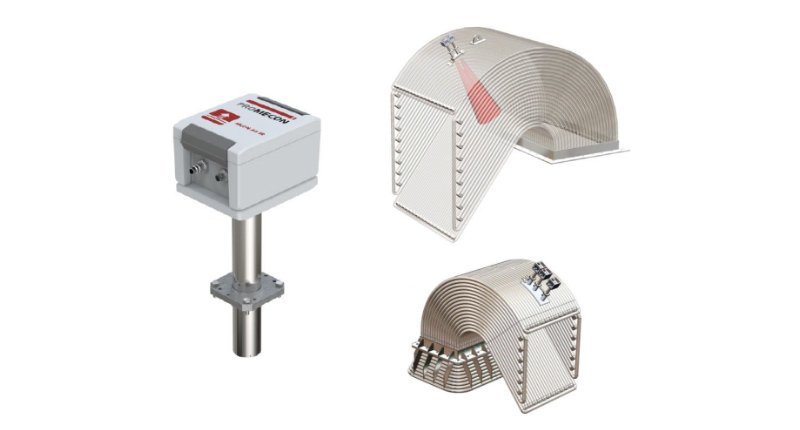
- Can be used even in high-dust environments by installing on one side of a duct, pipe, or furnace
- Simultaneously measures flow, concentration (CO, CO2, H2O), and temperature with a single unit
- Essentially drift-free—no calibration needed
- No supporting equipment needed (no pretreatment of target gases required)
Specifications
Flow/Temperature Specifications
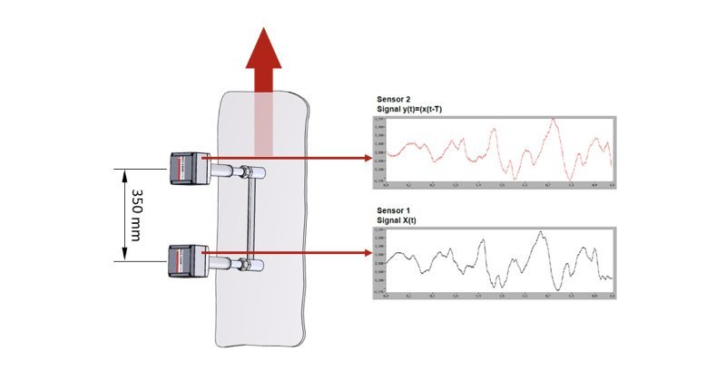
Two parallel sensors on one side of a duct allow continuous drift-free measurements of the velocity of off-gas velocity as hot as 2,500 °C.
| Measurement range |
3-100m/s |
|---|---|
| Accuracy |
Within ±2 % |
| Reproducibility |
Better than 99.95 % |
| Drift |
None |
| Linearity |
100% |
| Calibration |
Not required |
| Target gas temp. |
200–2,500 °C |
| Response time |
1 sec. |
| Waterproof rating |
IP66 |
| Ambient temp. |
Max50℃ |
Flow/Temp. Normally Below 1000 °C
Two parallel sensors on one side of a duct allow continuous drift-free measurements of off-gas velocity.
| Measurement range |
3–100 m/s |
|---|---|
| Accuracy |
Within ±2 % |
| Reproducibility |
Better than 99.95 % |
| Drift |
None |
| Linearity |
100% |
| Calibration |
Not required |
| Target gas temp. |
0–1,100 °C |
| Dust |
10 mg–3,000 g/m3 |
| Response time |
1 sec. |
| Sensor diameter |
25 mm (or 15 mm) |
| Sensor length |
1,150 mm |
| Sensor material |
Steel (1.4841) |
| Enclosure |
Rittal AE 1030.500 |
Concentration, Temperature
Two parallel sensors on one side of a duct allow continuous drift-free measurements of CO/CO2 concentrations and temperature and H2O concentrations in off-gas as hot as 2,500 °C.
| Measurement range |
3–100 m/s |
|---|---|
| Accuracy |
Within ±2 % |
| Reproducibility |
Better than 99.95 % |
| Drift |
None |
| Linearity |
100% |
| Calibration |
Not required |
| Target gas temp. |
200–2,500 °C |
| Response time |
1 sec. |
| Waterproof rating |
IP66 |
| Ambient temp. |
Max. 50 °C |
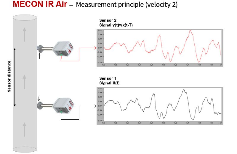
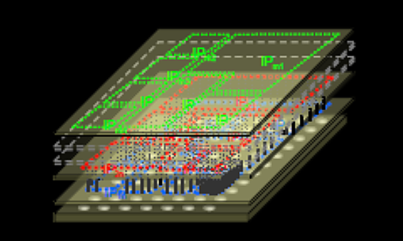
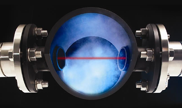
Principle
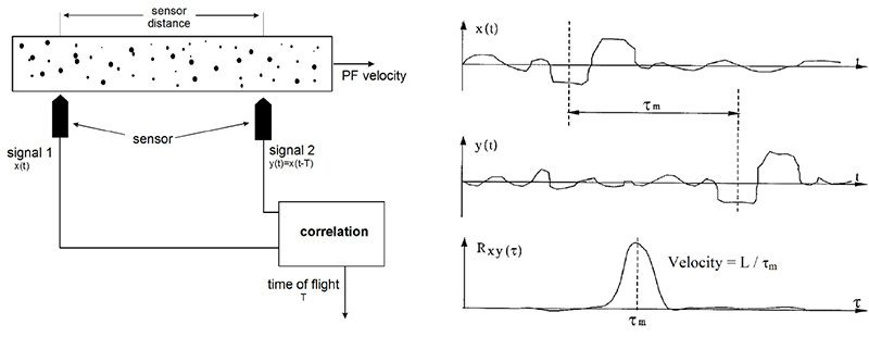
Flow Rate
The high-speed IR photodetectors of the two sensors detect IR intensity at infrared wavelengths (spectra) emitted by gas-borne CO and CO2 molecules.
Changes in intensity are reflected in signal waveforms and compared to determine the time shift, allowing calculation of flow velocity based on the distance between the sensors.
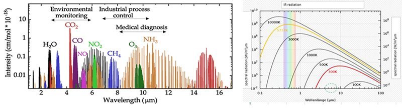
Concentration, Temperature
Based on the information provided by these high-speed IR sensors, the system detects infrared wavelengths (spectra) emitted by CO, CO2, and H2O at high temperatures and measures changes in IR radiation intensity of specific gases found in the target gas as the concentrations change.
*Infrared excitation wavelength intensity of specific gases measured are directly converted into their concentration.
To reduce the effect of other gases during measurement, a filter is used to remove wavelengths other than IR wavelengths of specific gases in the target gas.
Applications
・Steelmaking: converters :Visualization of hot gas flow at converter outlet for reuse (to conserve energy)
・Steelmaking: coke ovens :Visualization of hot gas flow at converter outlet for reuse (to conserve energy)
・Steelmaking: electric furnace :Measurement of electric furnace off-gas flow, concentration (CO, CO2, H2O), and temperature to optimize combustion
・Cement :Visualization of hot gas flow at kiln outlet for reuse (to conserve energy)
・Incinerators :Visualization of hot gas flow at incinerator outlet for reuse (to conserve energy)
・Lime :Visualization of hot gas flow at lime kiln outlet for reuse (to conserve energy)
・Boilers :Visualization of hot gas flow at boiler outlet for reuse (to conserve energy)
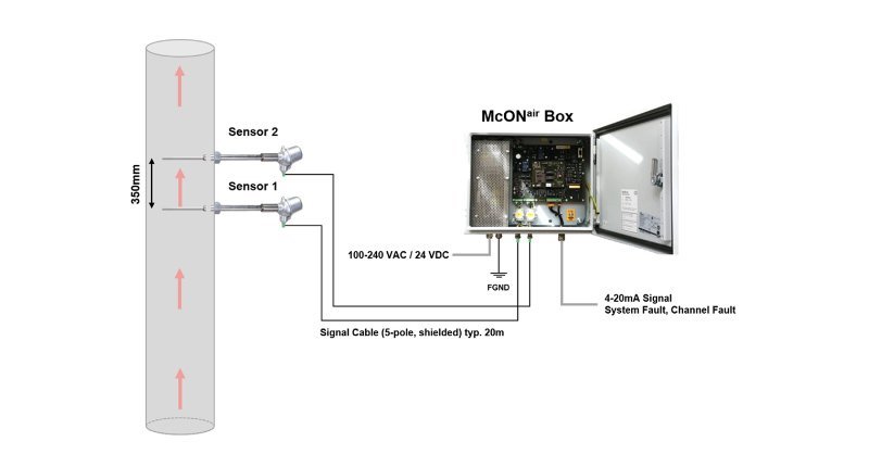
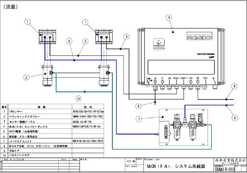
Structural Diagram
Flow
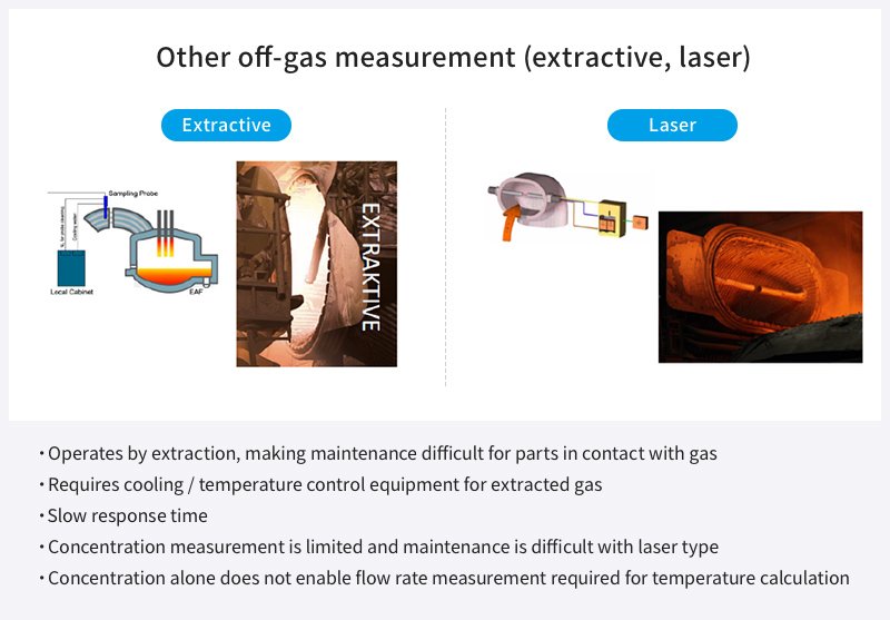
Competitive Comparison
For product inquiries, please submit the contact form.
Related products
-
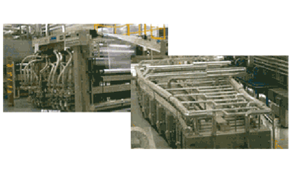
Textile and Film Equipment
Film Manufacturing Equipment -
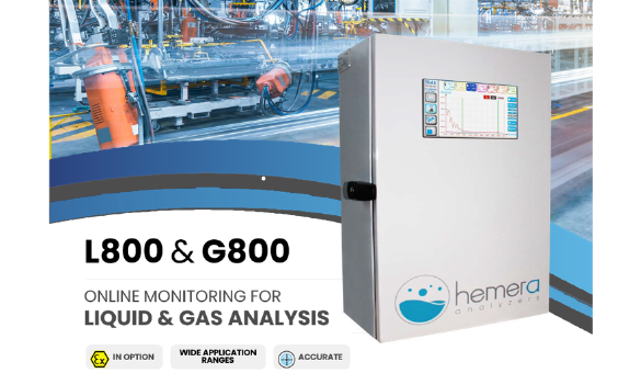
Measuring Equipment
Online Gas and Liquid Analyzers (G800/L800) -
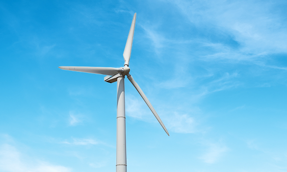
Power Generation Equipment
Wind Power -

Power Generation Equipment
Biomass Power -
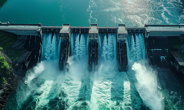
Power Generation Equipment
Hydropower -
Power Generation Equipment
Solar Power -
Environment and Preservation Equipment
Power Generation Equipment
Natural Pellets -
Textile and Film Equipment
HYPOX Polymer Removal Systems -
Textile and Film Equipment
Synthetic Fiber Production Equipment -
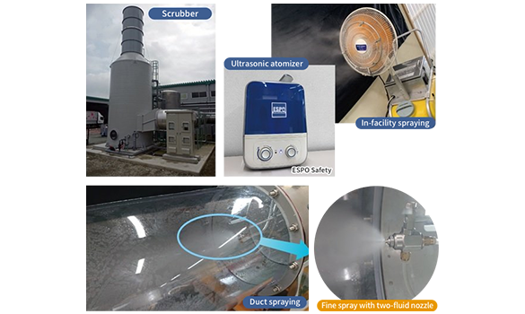
Environment and Preservation Equipment
NOZEPAL Industrial Deodorizers -
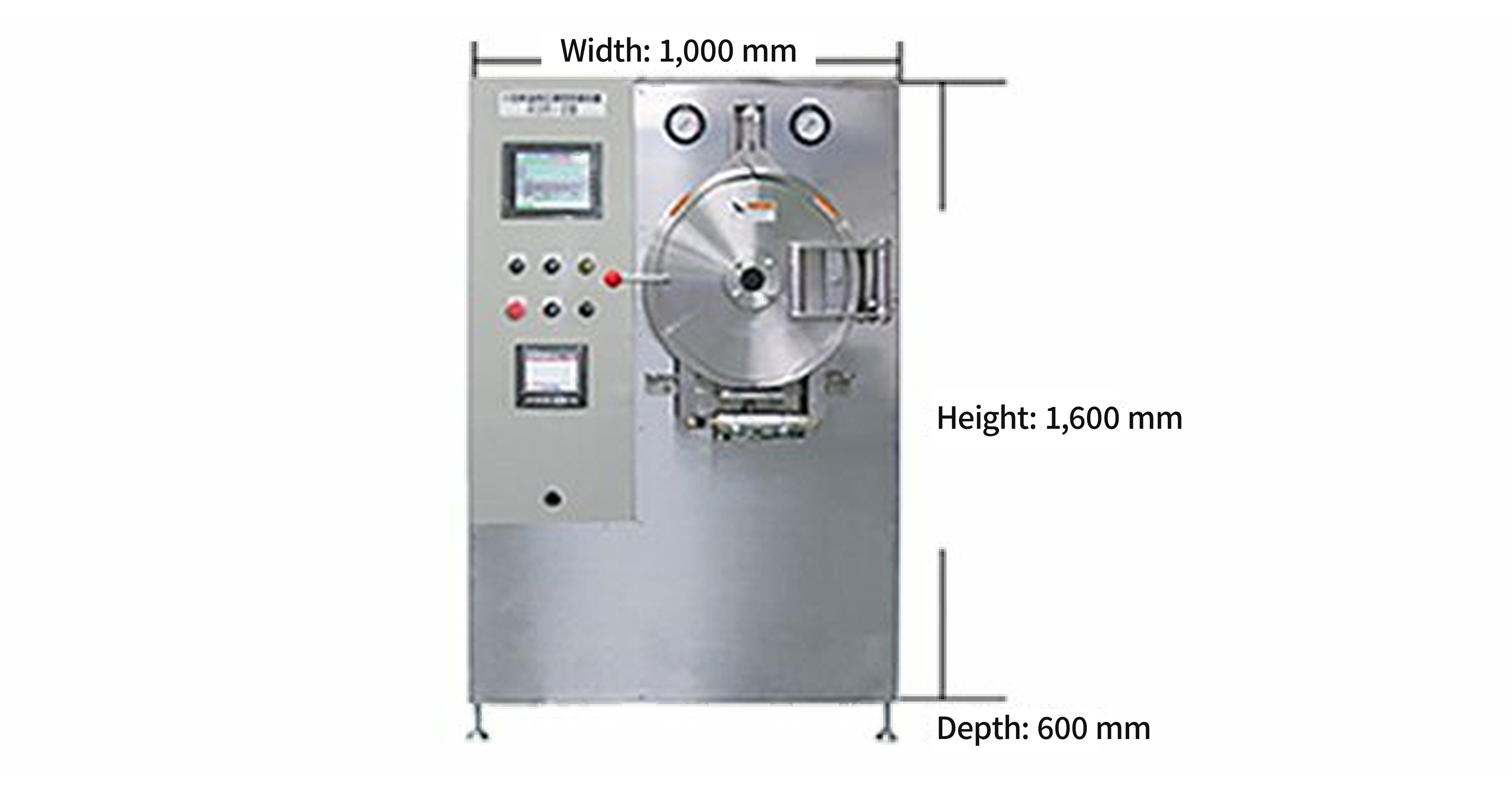
Food and Pharmaceutical Equipment
Compact, High-Temperature/Pressure Retort Sterilizers -
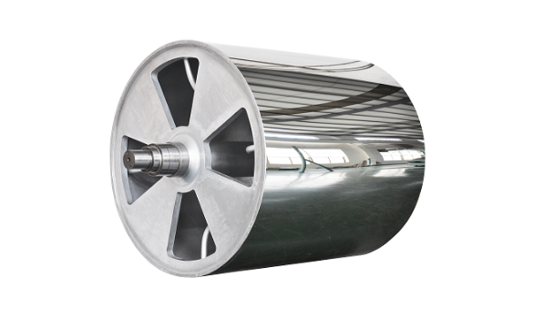
Textile and Film Equipment
Large Industrial Rolls -
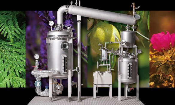
Food and Pharmaceutical Equipment
Essential Oil Decompression Steam Distillers -
Power Generation Equipment
General Industrial Machinery
Battery-Free Flywheel UPS Systems -
Semiconductors, Electronics
Semiconductor Contract Processing -
Measuring Equipment
McON IR Sensors -
Measuring Equipment
Environment and Preservation Equipment
Handheld Gas Leak Inspection System -
Measuring Equipment
Laser Gas Analyzers -
Measuring Equipment
Food and Pharmaceutical Equipment
DataTrace Micropack III -
Measuring Equipment
Food and Pharmaceutical Equipment
DataTrace Micropack RF -

Environment and Preservation Equipment
Automation, Digital Transformation
eve auto -
Measuring Equipment
Environment and Preservation Equipment
Seika Ecorator Diffuser Tubes -
Power Generation Equipment
Ultralight Solar Panels -
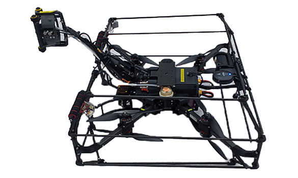
Measuring Equipment
Automation, Digital Transformation
UT Drone-Based Plant Inspection